Support & maintenance
This page describes how to troubleshoot and repair a Heliomotion tracker of the latest model (Tracker Z). For earlier models see the legacy support page.
![]()
Description
The software tool Heliocom is used to communicate with the tracker for service purposes. To use it, launch the program on a Windows laptop and connect it to the USB terminal on the tracker’s circuit board using a USB cable (Type-A Male to Type-A Male). Needs to be USB 2.0 or 3.0 cable, not 1.0, and USB cable length at most 1.2 meters. Alternatively, a Type-A Male to Type-C Female adapter can be placed into the USB slot to connect using a regular (Type-A Male to Type-C Male) mobile charging USB cable.
Program download: Heliocom v0.98G
Program description: Heliocom manual
If Heliocom is unable to connect then you need to restart the tracker first, by toggling its power off until the LED lights turn off. After connecting following a restart, you can press the stop button twice and wait a few seconds to stop GPS sync as well as pause automatic tracking.
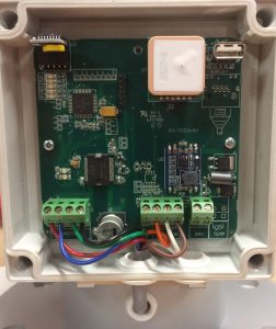
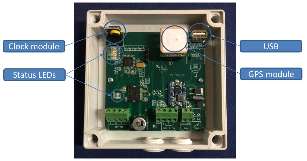
The circuit board has five LEDs that indicate the status of the tracker:
- Green (A) – Blinks to indicate that the tracker is powered and operational.
- Yellow (B) – Lit if the tracker has paused its operation due to being unable to rotate. See “Service Mode” sections for more information. Blinks to indicate rotation to either start or noon position.
- Orange (C) – Lit to indicate temperature alarm (for thermal installations). Blinks instead of green LED to indicate the clock battery is depleted.
- Blue (D) – Lit during GPS synchronization, which occurs at startup and dawn.
- Red (E) – Lit to indicate satellites were not found during the latest GPS synchronization.
A second set of two LEDs are found near the bottom of the circuit board: red and orange. The orange led is lit while the motor is running. The red led is not used.
The Heliomotion tracker’s operation is fully automatic. When powered on the tracker goes through the following steps to track the sun:
- The tracker waits until a GPS fix has been established to retrieve information needed to calculate the sun’s current position: latitude, longitude, date and time. This information is recalibrated every morning.
- The tracker rotates to face the sun’s present position.
- As the sun moves across the sky the tracker follows it, moving in intervals of 1.8 degrees every couple of minutes. After each movement the tracker positions itself 0.9 degrees ahead of the sun.
- The tracker continues to follow the sun until sunset or until its evening position is reached, which is 90 degrees after the noon position.
- After sunset the tracker returns to its noon position.
- Before sunrise the tracker rotates counterclockwise to the position where the sun will rise, 90 degrees or less depending on the season.
- The tracker awaits sunrise and then repeats the sequence from Step 4.
If a Heliomotion installation is left without power the wind may eventually rotate the framework to morning or evening position. The end stops will physically prevent the tracker from rotating far beyond these positions.
Note that the tracker follows the sun only when it’s above the horizon. This means it tracks 180 degrees during the summer half of the year and progressively less the closer the season gets to midwinter.
When the yellow LED (B) is continously lit it means the tracker has paused operation because it is unable to rotate. The tracker will automatically try to resume normal operation after 60 minutes (specified by Service Timeout parameter).
If the yellow LED (B) becomes continously lit as soon as the tracker is powered on, this is because the position sensor is not properly connected. If the yellow LED instead turns on continously after the blue LED (GPS sync) was lit then it indicates the clock module is faulty (invalid date/time even after GPS sync).
By connecting with Heliocom (v0.98A or later) the exact reason for the pause is shown, which can be one of the following messages:
Rotation errors
Message: “Unable to reach noon position”, “Unable to reach start position” or “Service counter limit reached”
These messages occur if the tracker has repeated been unable to rotate to its correct position and has therefore paused operation. This can be for instance because:
a) A permanent obstacle such as snow or vegatation is preventing rotation. Check for and remove any such obstacle.
b) A temporary obstacle such as heavy wind is interfering with proper rotation. This is normal behavior and tracker will automatically resolve this once the wind calms down. See “Obstacle Handling” section for more info.
c) Friction or an imbalance is making it difficult for the motor to rotate. See “Friction and Imbalance” section to check for any such issues.
d) The position sensor or its parameters may be faulty. See “Calibrating Position Sensor” section for instructions on how to check the sensor.
Position sensor error
Message: “Position sensor disconnected”
See pictures under “Calibrating Position Sensor” section for how the three wires between the position sensor and the main circuit board are to be connected. Make sure there is no short circuits between these wires. This error occurs at startup if the position sensor is completely disconnected or if the sensor wire (middle one on sensor board) is short circuited with the ground wire, making it appear as if the sensor is disconnected. Note that if instead the V+ wire is short circuited with the sensor wire the tracker cannot detect the wiring error and will end up rotating clockwise until the end stop prevents further rotation, as the sensor signals it is still in morning position.
Clock errors
Message: “Clock has stopped ticking”, “Clock has invalid time/date”, or “Tracker has not rotated in 24 hours”
In rare instances some clock modules may occasionally fail to update correctly or lose track of time. When the tracker automatically restarts it will reset the clock via the GPS network which typically resolves this issue. If this error persists then see “Changing Clock Battery” section for instructions on how to change the clock module.
If the tracker repeatedly encounters an obstacle that prevents it from rotating the tracker will pause its normal operation before trying to rotate again. The motor power is set to a low value (5 Nm) by default for safety reasons, allowing a person or obstacle to easily stop the rotation of the tracker without causing damage to the installation or injuries to any person. The default rotation speed is also set low (5 minutes for 180 degrees) for safety reasons. Parameters such as “Motor Power” and “Motor Speed” can be adjusted using the Heliocom software.
The “Service Count” and “Service Timeout” parameters visible in Heliocom are used for obstacle handling. Every time the tracker completes a rotation it updates the Position value to its new calculated position and checks the Sensor’s value to make sure it is within “Sensor Margin” degrees from its calculated Position. If the Sensor value deviates too far from the Position value, the tracker updates the Position value to the value read from the Sensor and increments an error counter.
The tracker then retries the rotation. If the tracker fails consecutively “Service Count” number of times, the tracker will pause its operation for “Service Timeout” number of minutes, going into service mode. Each time service mode is entered the Service Timeout is increased by 60 minutes up to 6 times (reset every morning).
Troubleshooting
Update to the latest Firmware version (v60 or later) to solve this issue.
In rare instances, some clock modules will occasionally reset themselves to their initial date (January 1st) during midnight, causing the tracker to move to morning position later then usual (calculating sunrise time as if it’s January 1st) before the date is automatically corrected by the morning GPS synchronization taking place. See “Updating Firmware” solution for details on how to solve this. Alternatively, replace the faulty clock module.
Check for and remove any obstacles that can hinder rotation to morning/evening positions, such as snow or vegetation.
Also check that the end stops are positioned correctly so as to not interfere with regular 180 degree rotation. The end stops are a safety feature to physically prevent the tracker from rotating beyond the morning/evening positions.
There should be a small (2-3mm) distance from the end stop and the fork arm when tracker is in morning/evening position.
Solutions
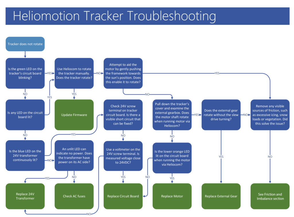
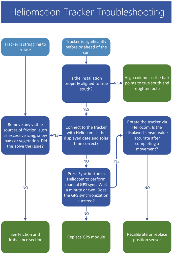
Friction or an imbalance of the framework may make it needlessly difficult for the tracker to rotate the framework. Check the list below for possible causes.
Panel balance
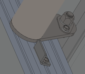
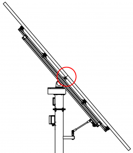
Make sure the panels are balanced in the middle of the angle brackets, as shown in the picture below. Also check that there is no extra weight attached to the framework. Microinverters can be mounted on the lower half of the framework without causing an imbalance issue, but string inverters must not be mounted on the framework. Imbalance will make it difficult for the motor to rotate the framework.
Rod support
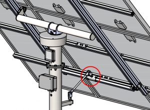
Make sure the rod support plate (circled in red) is oriented as shown in the picture below. If it is oriented towards the balk the fork joint cannot rotate properly and it will be difficult for the tracker to rotate.
Angle bracket orientation
The angle brackets (marked in red) need to be oriented as shown in the picture below. If they are rotated the other way around the balance point will be way off and it will be 5 times more difficult for the tracker to rotate.
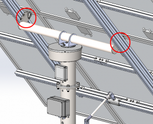
M16 bolts
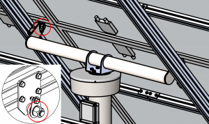
The two M16 bolts (circled in red) should not be tightened so much as to cause friction. They should only barely touch the M16 nylon washer. You can loosen the angle rod temporarily and tilt the framework up and down to make sure there is no resistance from the M16 bolts being screwed on too tightly.
24V transformer
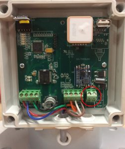
Use a voltage meter to confirm that the 24V transformer delivers close to 24VDC, even while the motor is running. The 24V voltage can be measured on the screw terminal circled in red below. If the voltage falls significantly during motor rotation the transformer needs to be replaced. If the voltage falls to for instance 12V the motor torque will be half as strong as when running at 24V.
Fork joint threads
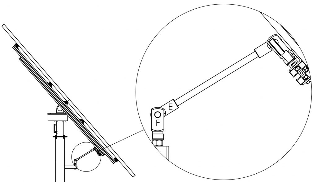
Both the Fork joints (F) and Clevis eye (E) rotate as the tracker rotates, so it is important that they are unscrewed half a turn on their threads to allow for the full 180 degrees of motion.
Fork joint lubrication
See the Maintanence -> Fork Joint Lubrication section for instructions on how to grease the rotating joints. Friction in this section may hinder rotation or cause a noise to occur during rotation.
Gear friction
Check inside the Drive Cover that the Front Plate of the External Gearbox does not push too hard on the External Gear so as to cause friction. It should be possible to rotate the External Gear by hand, although the motor is multiple times stronger than the force that can be applied by the hand. If the External Gear cannot be rotated by hand when the Front Plate is attached, but it can be rotated when the Front Plate is removed then this is the cause of the friction. If so then 4x M4 nylon washers can be added as extra distance underneath the 17mm white nylon bushings to remove the friction (the M4 washers used for the drive cover can be used for this purpose).
![]()
![]()
![]()
Slew drive
If the cause of the friction appears to come from the slew drive then see the “Slew drive” sections on this page for possible solutions.

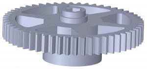

A replacement External Gear can be ordered using the Contact form.
Replace the gear as described below.
![]()
![]()
![]()
- Pull down the Drive Cover by first unscrewing three M4 bolts underneath the Drive Cover and four M4 bolts on the sides of the cover. Be careful not to drop any bolts. Tool: 2.5mm hex key (Allen wrench).
- Turn off the power to the tracker (preferably) so it doesn’t rotate when external gear/motor/sensor is not attached.
- Use a plier to cut the cable tie used for shortening the Motor’s wires.
- Unscrew the four M4 bolts attaching the Motor to the Front Plate and place the Motor on top of the Drive Cover. Tool: 3mm hex key.
- Take out the new External Gear so it is ready for use.
- Unscrew the four bolts connecting the Front Plate to the Back Plate of the external gearbox.
- Pull the Front Plate away sufficiently to remove the previous External Gear. Be careful so the plastic bushings do not fall away.
- Attach the new External Gear to the Position Sensor’s shaft first, and then attach it to the Slew Drive’s shaft. If the External Gear is a tight fit, use a plastic hammer to tap it all the way onto the shaft (some slew drive shafts are slightly larger than normal).
- Reattach the four screws holding the Front Plate to the Back Plate, making sure the External Gear is correctly attached on both sides.
- Make sure the Front Plate is not pressing against the External Gear, causing needless friction, by pushing the gear (~1mm) further onto the slew drive shaft using your hand (or two small screwdrivers if more force is needed).
- Reattach the Motor with four bolts, making sure the motor shaft goes into the slot in the Back Plate.
- If the External Gear’s attachment to the Slew Drive is broken the tracker will not rotate but the Position Sensor will rotate. Therefore, if the External Gear is changed after it has been worn out the Position Sensor will then need to be recalibrated. Perform the “Basic Calibration” steps as described in the “Calibrating Position Sensor” section of this page.
- Reattach the Drive Cover with its seven bolts.
- Turn the power to the tracker back on.
- The metal gear has slightly more friction than the plastic gear. Therefore it is recommended to increase Motor Power setting from 110 to 120 (+20% torque). See “Changing Motor Torque” section.
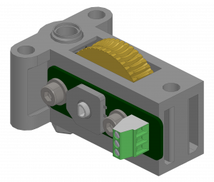

To calibrate the Position Sensor connect a laptop to the tracker via Heliocom (see Using Heliocom section). Make sure the Drive Cover is pulled down so that the Position Sensor is accessible.
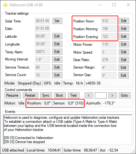

Heliocom displays two positional values: “Position” and “Sensor”. The unit for these values is in degrees relative to midday (noon) position (0.0), so morning position is -90.0 degrees and evening position is 90.0 degrees. Position is the calculated position the tracker relies on mainly, whereas Sensor is the value read from the Position Sensor that the tracker uses to check that it completes its rotations successfully.
There are three main parameters shown in Heliocom used for calibrating the Position Sensor: Position Noon, Position Morning, Position Evening. These specify the raw value read from the Position Sensor (0-1023) when moving clockwise to these three positions. They are used by the tracker to map what rotational position correspond to what sensor value (-90 to +90 degrees). There is also the Sensor Gap parameter that specifies the sensor lag in degrees when switching from clockwise to counter-clockwise rotation (typically 0.0-2.0 degrees).
The Position Sensor parameters have been factory calibrated. Therefore, only a Basic Calibration has to be performed when a worn out External Gear is replaced (and only if the gear is worn out where it attaches to Slew Drive). If on the other hand the Position Sensor or the Circuit Board have been replaced then the Full Calibration needs to be performed.
Basic Calibration
- The purpose of the Basic Calibration is to align the sensor to the slew drive, so that the sensor is in its middle position (~0.0 degrees) when the slew drive is in its middle/noon position (balk and angle rod are lined up)
- Use Heliocom to rotate the tracker until the Sensor value in Heliocom shows ~0.0 degrees after moving clockwise. So if for instance the sensor shows 10.0 degrees, then first move 15 degrees counter-clockwise and then 0.5 degrees at a time clockwise repeatedly until ~0.0 degrees is reached (this is done to avoid any potential sensor lag). This value must be close to the middle (512) of the sensor interval, specifically within 470-540, so that the sensor doesn’t go past its valid range in the morning or evening position.
- Remove the three screws holding the Position Sensor and then carefully unmount the Position Sensor from the External Gear while maintaining the worm gear’s position with your finger so that the worm gear doesn’t rotate (as that would change the position of the sensor).
- Use Heliocom to rotate the tracker to midday position (where the angle rod and the balk are aligned).
- Reattach the Position Sensor without changing its position more than necessary for reattaching it.
- Use Heliocom to rotate the tracker 5 degrees counter-clockwise and then 5 degrees clockwise to confirm that the Sensor is close to 0.0 degrees (plus/minus 1 degree) while the tracker is aligned to midday position.
- Reattach the Drive Cover and restart the tracker (Restart button in Heliocom or toggle power) to switch it back to automatic tracking mode.
Basic Calibration (without laptop)
- If no laptop is available it’s possible to approximate the sensor calibration by following these two steps.
- Rotate the external metal gear by hand until the Balk and M16 angle rod line up. The slew drive is now in its middle/noon position.
- Detach the Position Sensor from the metal gear and rotate it by hand so the flat edge of the potentiometer/shaft points towards the motor, as seen in the picture above. This is close to the middle/noon position of the sensor. Then reattach the sensor back to the external gear with the 3xM4 bolts. Make sure to avoid changing the sensor’s position while reattaching it.
Full Calibration
- Perform all steps of the Basic Recalibration.
- Click on the “Test” button in Heliocom. Heliocom will then automatically perform the following actions:
- Set Sensor Gap parameter to 0 and rotate +5 deg to refresh sensor reading without any potential sensor gap.
- Rotate to exact noon position.
- Rotate -90 to morning position, then -5 and +5 to remove any sensor gap.
- Update Position Morning parameter.
- Rotate +90 to noon position and +90 to evening position. Updates Position Evening parameter.
- Rotate to exact noon position.
- Rotate +10 then -10 to get sensor gap and update Sensor Gap parameter.
- The Position Sensor is now calibrated and you can press the “Restart” button in Heliocom to have the tracker resume automatic tracking mode.
![]()
![]()
Spare parts for Position Sensor are no longer available due to company shut down.
The firmware of the solar tracker can be updated using the USB connection and Heliocom. The firmware version can be seen when connected to the tracker using Heliocom, ex “v4650-58” means version 58 is installed. Note, this firmware update cannot be used with earlier models (Tracker S and Tracker XL). These models can be upgraded to the new circuit board.
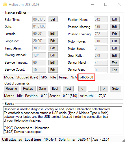

To update the firmware download and unzip the following software:
Heliocom: Heliocom
Bootloader: Bootloader
Heliofirmware: Heliofirmware v63 (previous version v62)
Log: Software update log
1. Run Heliocom and the Bootloader (HIDBootloader.exe) on a laptop. Heliocom is used to communicate with the tracker and the Bootloader is used to update the firmware.
2. Unscrew the lid to the tracker’s circuit board using the screwdriver.
3. Connect the USB cable from the laptop to the USB port on the circuit board. Heliocom will then automatically connect to the tracker.
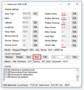

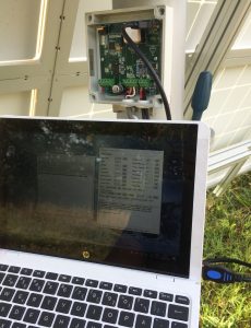

4. The solar tracker has four unique settings used for calibrating its Position Sensor. Please make a note of these unique values seen in Heliocom: Position Noon, Position Morning, Position Evening, and Sensor Gap. These settings will need to be manually restored after the update is complete since they will be overridden with default values.
5. In Heliocom, click the ”Boot” button and the tracker will disconnect from Heliocom and instead connect to the Bootloader application (wait a few seconds for the reconnect to happen or plug the USB in and out).
6. In the Bootloader application, click the open icon to the left of the top menu. Browse and open the latest firmware (.hex file) for the tracker that was downloaded and unzipped earlier.
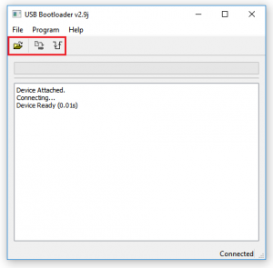

7. Click the ”Erase/Progam/Verify Device” button (second from the left) to perform the firmware update. If the update would fail for any reason restart the Bootloader and try the firmware update again.
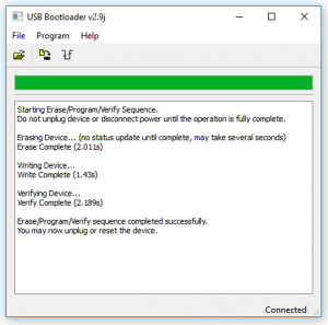

8. When the update is complete click the ”Reset” button to the right of the menu to restart the tracker which disconnects from the bootloader and reconnect to Heliocom. Note that the version number seen in Heliocom will now have changed to read “v4650-61”.
9. In Heliocom, click 2 times consecutively on the ”Stop” button and wait a couple of seconds for the tracker to stop. The first click aborts the automatic GPS synchronization performed at startup and the second click pauses automatic tracking.
10. Change the four settings written down earlier: Position Noon, Position Morning, Position Evening, and Sensor Gap. To change a setting first click the ”Edit” button next to that setting. The field then becomes editable and the button changes name to “Set”. Type the new value into the field and click the “Set” button to submit the new setting to the tracker. Do this for all four unique parameters.
11. Click on the ”Restart” button in Heliocom to allow the tracker to resume normal operation.
12. Disconnect the USB cable and put the lid back on the box.
It is recommended not to increase Motor Power above the default 120 setting, because this setting already provides 5x the torque needed to rotate that tracker under normal circumstances (when there is no wind). Increasing the Motor Power will increase wear on the External Gear and may worsen any underlying issue that is causing increased friction. Instead, you should look through the “Friction and Imbalance” section to find and resolve any potential issue interfering with normal rotation.
The motor power setting can be changed with Heliocom if more or less motor torque is needed. On the 7003 board the default setting is “120” (previously 110) which translates to 24 watt at Motor Speed 3 (default). Motor Power setting translates to power output as follows: 90 = 10W, 100 = 15W, 110 = 20W, 120 = 24W, 130 = 26W, 140 = 30W, 150 = 35W, 160 = 39W. Note that the default included transformer is rated for max 30W (power setting 140).
On the 7004 board the default setting is “14” which corresponds to 20 watt at Motor Speed 30 (default). Motor Power setting translates to power output as follows: 3=4W, 6=6W, 9=10W, 10=12W, 12=15W, 14=20W, 15=24W, 17=29.5W, 18=32W, 20=40W.
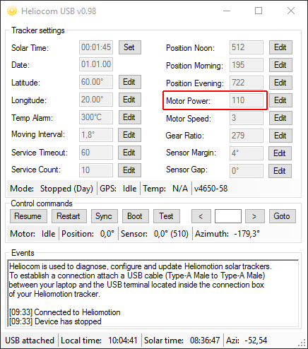

If motor power is insufficient the motor will give of a sound as it’s unable to rotate the motor shaft. If the motor power is set too high (>160) motor driver on the circuit board will not allow the motor to run until the power setting is reduced, preventing damage to the motor.
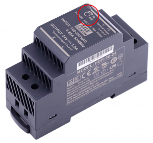
Motor strength can also be increased by raising the operation voltage of the circuit board, by turning the voltage adjustment potentiometer on the 24VDC transformer clockwise. Allowed voltage range of circuit board is 10-29 VDC. Adjusting the transformer from 24 VDC to 29 VDC will increase the motor strength linearly by 20%.

If necessary, a replacement YK60HB65-03A stepper motor can be ordered from Shenzhen Yako Automation Tech (Yakotec). If another Nema23/24 stepper motor is used the Motor Power setting will need to be adjusted to get the desired torque/power consumption.
As a redundancy feature the tracker is equipped with a replaceable clock module which includes a backup battery (3V lithium cell). Should the GPS module or GPS network fail the tracker can still keep operating for many years using this clock and the stored latitude/longitude settings. Note that the tracker operates on solar time, which is different from local time. The sun always reaches its highest elevation at 12:00 solar time.
The clock module is located here on the circuit board:
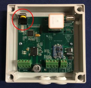

If the battery is depleted the orange LED on the circuit board blinks instead of the green LED.
The tracker will continue working even after the battery depletes. It is a redundancy in case the GPS module fails in which case the tracker will rely solely on the timekeeping of the clock module.
The clock module used is a standard “DS3231 RTC Clock Module for Raspberry PI”.
A replacement clock module can be purchased from for instance AliExpress.
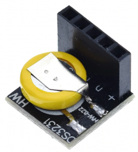

Turn off power to the tracker when replacing the RTC module. When restarted the tracker will automatically update the clock settings from GPS data and use the new module for timekeeping.
If the GPS module does not manage to synchronize to the GPS network the red LED on the circuit board is lit. The tracker can continue working for years even if the GPS module fails as it will then rely solely on the clock module for time keeping. However, the time keeping of the clock module will gradually go out of sync over the years and so a faulty GPS module should be replaced.
The GPS module is plug-and-play. Just remove the faulty module from its pins on the circuit board and plug in the new one. Model of GPS module is: K.TEL VK2527U7G5L.
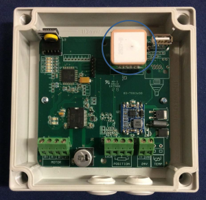

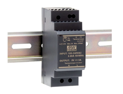
The tracker can be powered by any 24 VDC transformer able to provide at least 1.5A of current. The transformer supplied with the installation is the DIN-rail mounted Mean Well HDR-30-24. Make certain to turn off all AC and DC power to the distribution box before replacing the transformer.
A replacement 24VDC transformer (model HDR-30-24) can be purchased for instance from AliExpress.

Turn off power to the tracker before changing the circuit board. Make sure each wire is connected to the correct screw terminal as shown in the picture below before turning the power back on again.
A replacement circuit board can be ordered via the Contact Form.
Specify the unique serial number of the tracker (seen on a label inside of the circuit board box, ex “Z19200”) and we will supply the circuit board with factory settings for your tracker (otherwise sensor calibration will be necessary).
Due to business shut down there are no spare circuit boards available.
If the slew drive friction appeared when temperature dropped below zero then it is caused by ice. Water has leaked into the slew drive and frozen there, making the gear unable to rotate. Recommended solution is to power off the tracker. Once average nighttime temperatures go above zero, turn the tracker’s power back on and it will resume normal operation. The water that has leaked into the drive will evaporate on its own over time.
See the “Slew Drive Water Protection” section for how to prevent water from entering the drive.


If a cog in the Slewing gear of the slew drive is broken the drive will not rotate past that section when the Worm gear is turned. Rather than replacing the drive, it is possible to renew the cogs (a single time) by instead using the cogs on the opposite side of the drive. Because the drive only rotates 180 degrees during normal operation the cogs on the opposite side will be unused, and the worm gear rotating the cogs on the slewing gear is deliberately made in a stronger material so that part will not be damaged. Here are instructions on how to do this.
First, the following steps can be taken to confirm that this solution will work:
1. Unhook the fork joint, tilt the framework horizontally and strap it down so it stays horizontally using a rope it using for instance a cargo strap.
2. Rotate the drive manually via Heliocom to confirm that the 180 degrees of previously unused cogs on the opposite side of the drive are working properly. If a broken cog prevents rotation before the tracker can reach the unused cogs, help the drive get past that section by turning the framework by hand so that the worm gear reaches the next usable cog.
Then, perform the following steps:
1. Remove the panels, framework and fork. Then turn the fork 180 degrees compared with how it was previously attached. Reattach the fork, framework and panels.
2. Carry out the steps in the “Calibrating Position Sensor – Basic Calibration” section to recalibrate the sensor.
Sometimes relubricating the slew drive through the grease nipple won’t be enough to reduce the internal friction of the drive. This is likely because one or both of the Bearings holding the Worm Gear has corroded due to water ingression. This section describes how to open the drive to clean the bearings to remove the internal friction of the drive, as an alternative to replacing the Slew Drive.


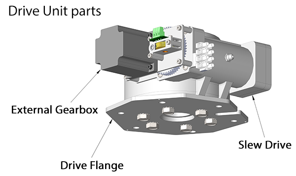

- Power off the system and remove everything mounted on top of the solar tracker. Open up the drive cover hood and remove the drive cover lid on the top of the tracker. Loosen the 6x M10 nuts and the 7 wires that connect to the drive unit (as well as any cable ties).
- Bring only the drive unit indoors and place it on the side (bolts facing towards you) on a work bench.
- Remove the 6x M10 bolts connecting the Drive Flange to the Slew Drive. Fastening the Drive Flange in a vise can make this simpler.
- Remove the Drive Flange and turn the Slew Drive upside down.
- Remove the 2x M6 bolts on the Slew Drive (underneath the Drive Flange).

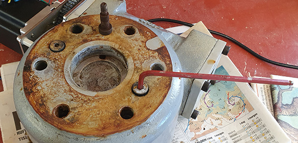
- Lift the Housing to separate it from the Slewing Gear.

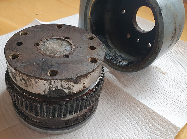
- Remove the External Gearbox from the Housing.
- Use a rubber hammer or similar tool to loosen the Worm Gear (with attached Bearings) and pull it out. Note: The Worm Gear can only be pulled out from that side of the drive where the External Gearbox was attached and only after the Slewing Gear has been removed.
- Separate the Conical Bushings from the Roller Bearings, using for instance a vice and a plastic hammer. Typically, one of the two Conical Bushings will remain in the Housing as the Worm Gear is pulled out.

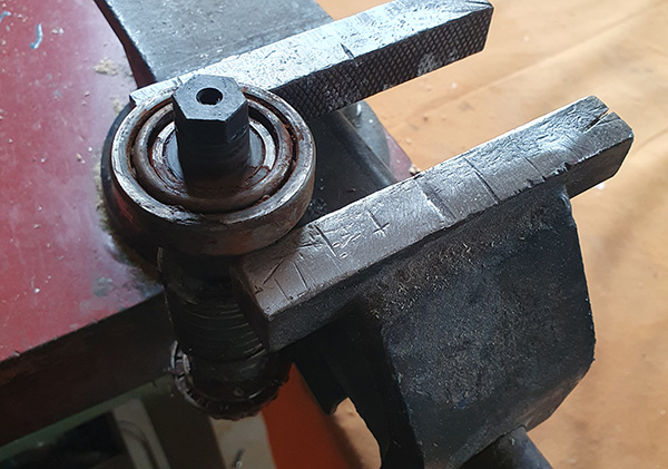
- Examine the Bearings on the Worm Gear. If they are corroded and won’t rotate properly this is the source of the friction.

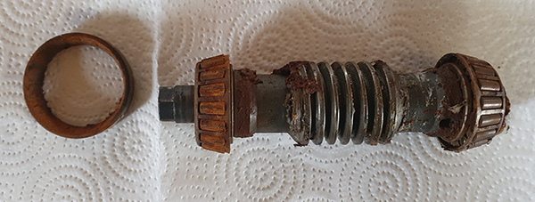
- Submerge the Bearings (and attached Worm Gear) in a rust dissolver (such as undiluted distilled white vinegar) for at least 30 minutes.
- Clean the corroded Bearings to remove the rust particles that cause the friction. Wipe the rust away with a cloth as you try to get all of the rollers in the Bearings to roll. Wash it again in the dissolver bath, clean it and repeat until the rust particles are removed and the Bearings can roll without much friction.

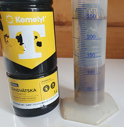
- Also clean the two Conical Bushings. One of them typically remains in the Housing and is easier to clean if the Adapter (square flange) is removed.
- Make sure the Worm Gear is clean and dry. Then reapply grease (see “Slew Drive Relubrication” section for suggested Grease) to the two Bearings, the Worm Gear, and to the supporting Conical Bushings. Rotate the Bearings to ensure even distribution of the lubricant.
- While the Housing is accessible, it’s recommended to add a 3mm drainage hole to the bottom of the Housing, to allow any water that potentially enters the drive to leak out. This hole should connect to the ditch on the inside of the Housing, surrounding the flange where the Slewing Gear attaches to the Housing, as this is the lowest point of the drive where water will accumulate. The drilling depth is 15mm. It can be drilled with a power drill, but it’s easier to drill it using a pillar drilling machine.

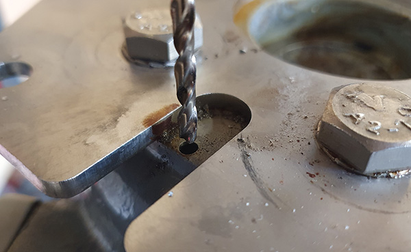
- Reattach the cleaned and greased Worm Gear to the Housing, including the Conical Bushings.
- Reattach the 3mm back plate of the External Gearbox to the drive, making sure not to tighten the bolts so much as to cause friction when the Conical Bushings are pressed against the Bearings on the Worm Gear. Note: the manufacturer sometimes adds one or more 0.1mm metal plates behind the Adapter to prevent the Worm Gear from being squeezed too tightly when the bolts are tightened.
- Place the Housing onto the Slewing Gear so that the 2x M6 positioning bolts can be screwed in. They make sure the Slewing Gear is centered inside the Housing.
- Try rotating the Worm Gear using the External Gear to make sure the drive rotates without much friction.
- Reattach the Drive Flange to the Slew Drive using the 6x M10 bolts. Use of Loctite on these bolts is recommended.
- Reattach the External Gearbox (and Motor).
- Go through the “Slew Drive Water Protection” section on how to prevent water from entering the slew drive.
- Bring the repaired Drive Unit back outside to the installation site and reassemble all parts of the system.
Maintenance
Every couple of years long-life grease should be reapplied to all rotating sections, including: the threads of the two fork joints (F), threads of one of the two clevis eyes (E), contact surfaces between fork joints (F), clevis eyes and rotating shaft that locks the clevis eye to the fork joint. This reduces friction which can otherwise cause noise to occur during rotation. Depending on weather, this process may need to be repeated every couple of years to keep friction low.


A hammer and a nail driver (or similar tool) may be needed to remove the pin from the fork joint.
Make sure the two fork joints (F) are unscrewed at least half a turn to allow for full 180 degree range of motion. The clevis eye (E) also rotates slightly, so it too needs to be unscrewed half a turn so as to not interfere with the rotation.
Slew drives are supplied fully lubricated but as they are used they may need to be relubricated after a number of years in service to keep drive friction low. Recommended grease, according to manufacturer, is listed below.
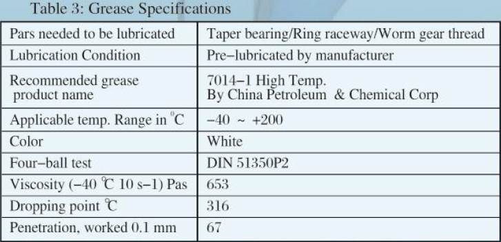

Go through the following steps to relubricate the drive.
- Detach the angle rod (threaded M16 rod) and strap the framework down horizontally. This is done both to gain better access to the grease nipple when in evening position and to make sure the friction does not come from the framework attachment points. Next, attempt to rotate the tracker manually using Heliocom to determine if the source of the friction actually comes from the slew drive. During factory test the slew drive is rotated with 2 watt (motor setting 40) to make sure there are no needless friction in the gears. An assembled PV-6 requires about 8 watt (motor setting 80) to rotate reliably (when there’s no wind). The default setting is 24 watt (motor setting 120). If the drive rotates fine when the angle rod is detached check for any imbalances or friction areas around the angle rod’s attachment points before reattaching the angle rod. A significant imbalance over a number of weeks may potentially cause the slew drive gears to become jammed or have increased friction due to a lack of grease. Remove the imbalance to avoid this happening again and continue on to the next step.
- Remove the drive cover to expose the grease nipple of the drive. If the drive can be rotated via Heliocom to any degree then it’s not necessary to also remove the external gearbox, so you can skip the next step.
- If the drive cannot be rotated via Heliocom, then remove the external gearbox, including the External Gear to expose the hexagon shaft of the drive (unless you have a tool that allows the drive to be rotated from the hole on the opposite side of the slew drive).

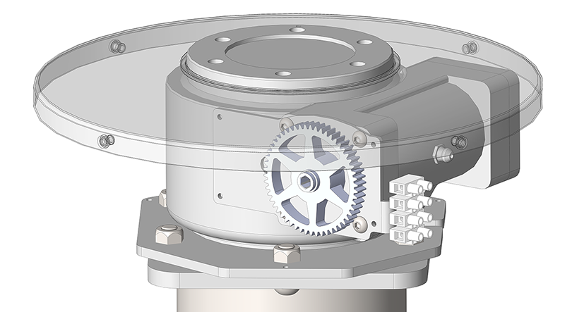
Unjam the drive by turning the slew drive shaft in the direction opposite of the jam (CW wrench turn from motor side = CW rotation) using a pipe wrench or similar tool. Once unjammed relubricate the drive by adding a single pump of grease through the grease nipple(s) using a grease gun.

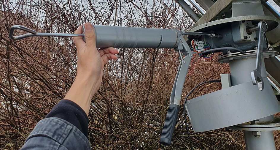
Rotate the shaft a few degrees CW and CCW to spread the grease around sufficiently to lower the friction to the point where the motor can rotate the tracker (pump in more grease if necessary). Then reattach the external gearbox so the tracker can be rotated via Heliocom. - Rotate the drive via Heliocom between morning and evening position, adding one pump of grease every 45 degrees (for a total of 6 times), to spread the grease around the drive gears. Reattach the drive cover and angle rod. Then restart the tracker to resume normal operation.
- If drive friction is not lowered despite relubricating the drive then try the solution outlined in the “Slew Drive Cogs” section.
- If friction is still not lowered then opening the drive to remove the source of the friction is another solution. See the “Slew Drive Rust Removal” section.
- If none of these solutions work then replace the slew drive. The model of the slew drive is SE3-62-H-16R, produced by Xuzhou Wanda Slewing Bearing (XZWD).
Under certain circumstances water can ingress into the slew drive. A symptom of this is that the slew drive freezes when temperature drops below zero degrees (see “Slew Drive Freezing” section). If not resolved, the water will eventually start corroding the Worm Gear, causing increased friction of the drive (see “Slew Drive Rust Removal” section).
To prevent water from leaking into the slew drive a self-adhesive sealing strip (combined with silicone glue) can be placed outside of the slew drive flange on the top of the drive cover. The sealing strip only needs to be a few millimeters high to prevent water (melting snow, etc) from entering the gap between the slew drive flange and the drive cover. Make sure to clean the surface area so there’s a good bonding surface for the glue. Add a rib of silicone glue around the outer side of the sealing strip to make sure it is water tight and stays in place.
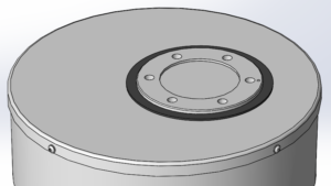

Alternatively, if a suitable sealing strip can’t be found the silicone adhesive can be applied directly around the flange provided that the flange is first greased so that the adhesive will only attach to the cover and not to the flange. The steps for this are outlined below:
1) Clean the lid around the flange to get a good bonding surface.
2) Add silicone grease to the sides of the flange (to prevent the silicone adhesive from attaching to that surface).
3) Use a suitable tool to add a rib of silicone adhesive around the entire flange and surrounding cover and let it dry for 12 hours while the tracker is not rotating (turn it off).
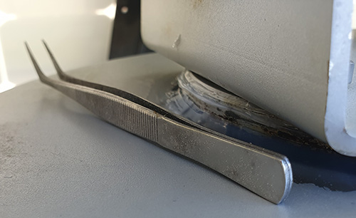

4) The silicone will form a near perfect seal around the flange and it will come loose from the flange due to the grease once the tracker is powered back on.
For some models there is insufficient space between the top of the drive cover and the fork to create the silicone seal. In this case remove the 3xM4 bolts from the bottom of the drive cover and push it down to make room for applying the silicone grease and adhesive. Then, after the silicone adhesive has cured glue three 5mm thick bushings (can be made by gluing 3 sets of 3x M8 washers together) to the inside of the bottom of the drive cover around the three small holes where the bolts are attached. This will lower the drive cover 5mm, exposing the flange sufficiently so that the silicone adhesive won’t be worn away when the tracker rotates.
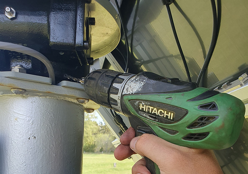
A third solution is to drill a 3mm drainage hole in the bottom of the slew drive using a power drill. Any water that enters the drive will then leak out of the hole before the water level gets high enough to reach and corrode the gears or bearings. Suggested hole placement and angle is shown below. This area contains a ditch between the Slewing gear and the Housing where water first accumulates. Drill depth ~10mm until the ditch is reached.
