


Support
This page describes how to troubleshoot and repair a Heliomotion tracker.
![]()
Description
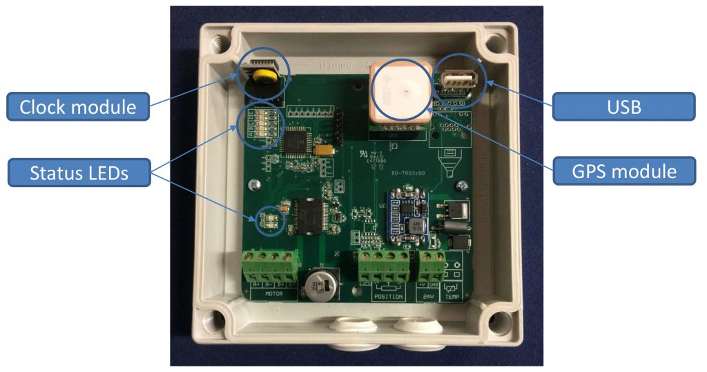
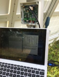
The software tool Heliocom is used to communicate with the tracker for service purposes. To use it, launch the program on a Windows laptop and connect it to the USB terminal on the tracker’s circuit board using the USB cable provided (Type-A Male to Type-A Male).
Program download: Heliocom
Program description: Heliocom manual


The circuit board has five LEDs that indicate the status of the tracker:
- Green (A) – Blinks to indicate that the tracker is powered and operational.
- Yellow (B) – Lit if the tracker has paused its operation due to being unable to rotate. Blinks to indicate movement to either start or noon position.
- Orange (C) – Lit to indicate temperature alarm (for thermal installations). Blinks instead of green LED to indicate the clock battery is depleted.
- Blue (D)– Lit during GPS synchronization, which occurs at startup and dawn.
- Red (E) – Lit to indicate satellites were not found during the latest GPS synchronization.
A second set of two LEDs are found near the bottom of the circuit board: red and orange. The orange led is lit while the motor is running. The red led is not used.
The Heliomotion tracker’s operation is fully automatic. When powered on the tracker goes through the following steps to track the sun:
- The tracker waits until a GPS fix has been established to retrieve information needed to calculate the sun’s current position: latitude, longitude, date and time. This information is recalibrated every morning.
- The tracker rotates to face the sun’s present position.
- As the sun moves across the sky the tracker follows it, moving in intervals of 1.8 degrees every couple of minutes. After each movement the tracker positions itself 0.9 degrees ahead of the sun.
- The tracker continues to follow the sun until sunset or until its evening position is reached, which is 90 degrees after the noon position.
- After sunset the tracker returns to its noon position.
- Before sunrise the tracker moves to sunrise position or to morning position, which is 90 degrees before the noon position.
- The tracker awaits sunrise and then repeats the sequence from Step 4.
If the tracker encounters an obstacle that prevents it from rotating the tracker will pause its normal operation before trying to rotate again. The motor power is set to a low value (5 Nm) by default for safety reasons, allowing a person or obstacle to easily stop the rotation of the tracker without causing damage to the installation or injuries to any person. The default rotation speed is also set low (5 minutes for 180 degrees) for safety reasons. Parameters such as motor torque, motor speed and pause duration can be adjusted using the Heliocom software.
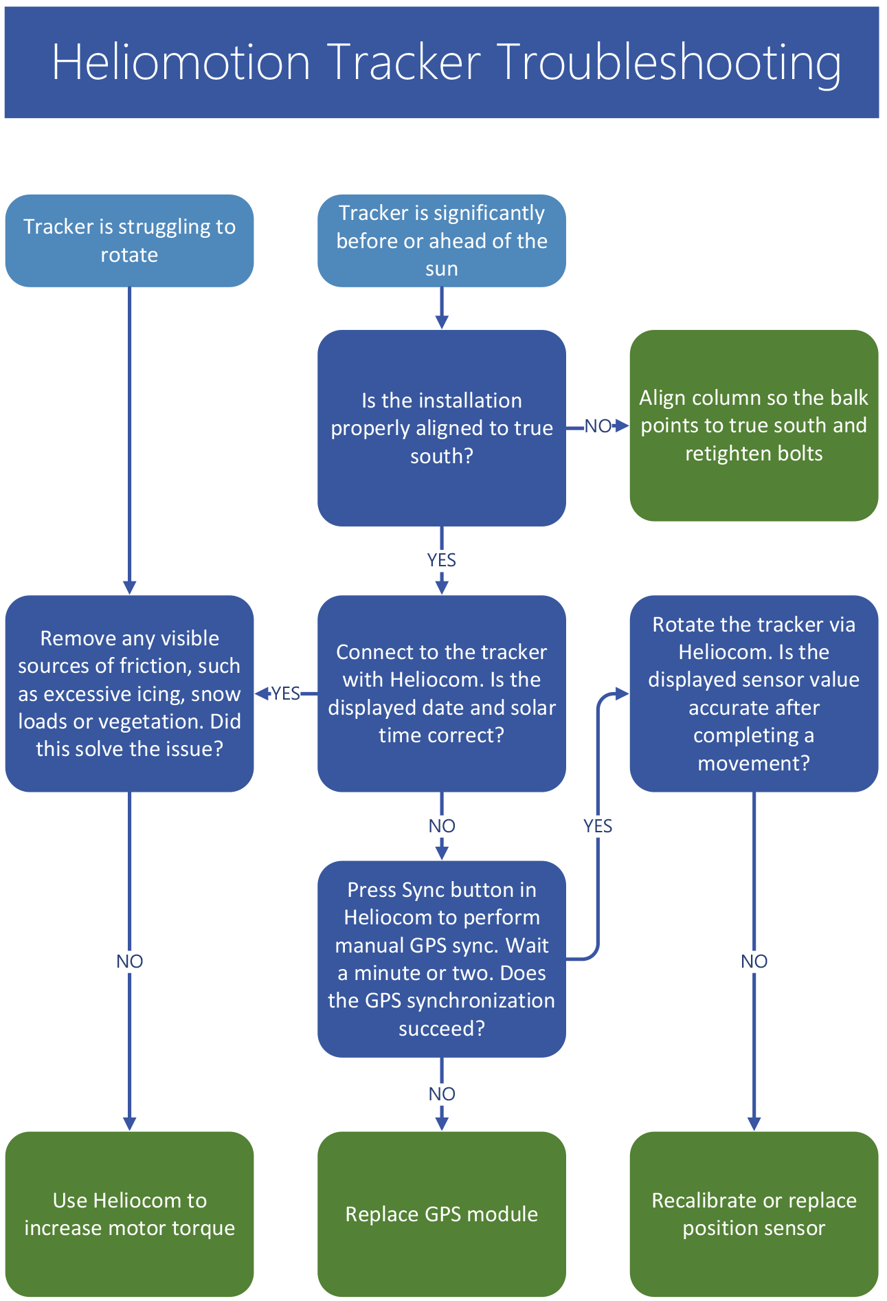
Troubleshooting
Solutions (in green) are described in detail lower down on this page.
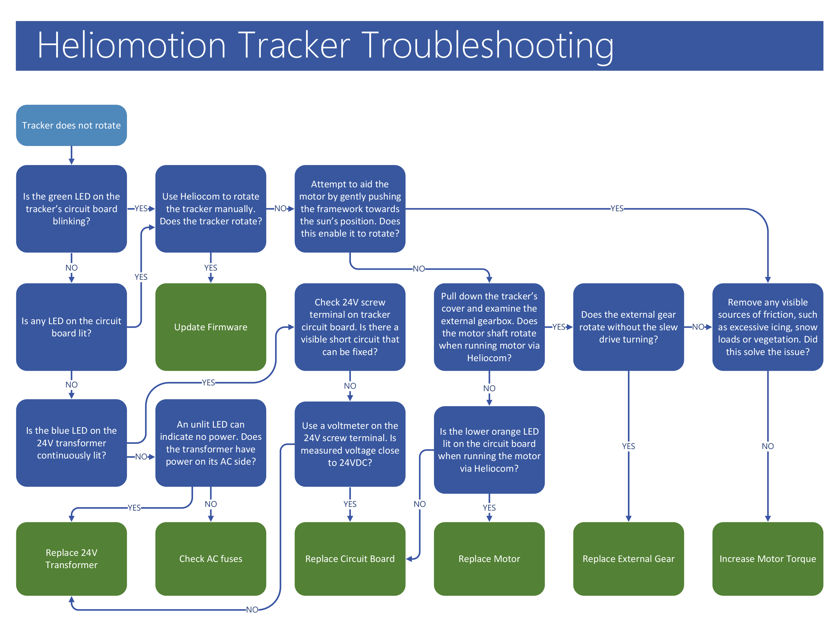
Solutions (in green) are described in detail lower down on this page.
Update to the latest Firmware version (v60) to solve this issue.
Some GPS modules sometimes give an incorrect date value (January 1st) when the daily GPS synchronization is performed in the morning. When this happens the tracker moves to the morning position later than usual (calculating sunrise time as if it’s January 1st) before the date is automatically corrected by another morning GPS synchronization taking place. See Updating Firmware solution for details on how to solve this.
Solutions
The Position Sensor moves in lockstep with the slew drive. If this is no longer the case (for instance if the Position Sensor or the External Gear has been replaced), then the sensor needs to be recalibrated.
To calibrate the Position Sensor first connect to the tracker via Heliocom.
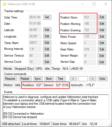
Heliocom displays two positional values: “Position” and “Sensor”. The unit for these values is in degrees relative to noon (midday) position (0.0), so for instance morning position is -90.0 degrees. Position is the calculated position the tracker relies on mainly, whereas Sensor is the value read from the Position Sensor. When powered on the tracker reads the Sensor value from the Position Sensor and assigns it as its current Position. Every time the tracker completes a rotation it updates the Position value to its new calculated position and checks the Sensor’s value to make sure it has not deviated too much from its calculated Position. If the Sensor value deviates too far from the Position value, the tracker updates the Position value to the value read from the Sensor.
There are three main parameters shown in Heliocom used for calibrating the Position Sensor: Position Noon, Position Morning, Position Evening. These specify the raw value read from the Position Sensor (0-1023) when moving clockwise to these three positions. They are used by the tracker to map what rotational position correspond to what sensor value (0-180 degrees).
- Use Heliocom to rotate the tracker to noon position (where the angle rod and the balk are aligned). Check the raw sensor value printed in Heliocom when the movement completes. If it is between 460-550 then that is fine and you can skip step 2.
- If the sensor value is outside the 460-550 range then rotate the tracker until the sensor value is close to 512 (the middle of its 0-1023 range). Then open up the Drive Cover after first disconnecting the USB cable so it’s not in the way when the Drive Cover is pulled down. Next, unscrew the three screws fastening the Position Sensor, and then temporarily remove the Position Sensor along with the shaft that connects it to the External Gear, leaving it to hang in the three electrical wires still attached to the Sensor. Finally, rotate the tracker back to the noon position and then reattach the Position Sensor. Make a small (0.1 degree) rotation to confirm the sensor value is inside the 460-550 range before closing the Drive Cover.
- There is a slight difference in the sensor value read when moving clockwise or counterclockwise to the same position. All three sensor parameters should specify the sensor value which is read from a clockwise movement to the Morning/Noon/Evening position. Therefore, it is best to rotate 5 degrees counterclockwise from noon position and then back clockwise to the exact noon position to get the most precise value. It’s possible to rotate the tracker in steps as small as 0.1 degrees.
- Update the Position Noon parameter to the raw value Heliocom display when rotating the tracker clockwise to noon position (needs to be within 460-550 range).
- Rotate 95 degrees counterclockwise and then 5 degrees clockwise. Then update the Position Morning parameter to the displayed raw sensor value for this position.
- Rotate 180 degrees clockwise. Then update the Position Evening parameter to the displayed raw sensor value for this position.
- The Position Sensor is now calibrated and you can press the “Restart” button in Heliocom to have the tracker resume automatic solar tracking.
If the Position Sensor does not function correctly a replacement Sensor can be ordered via the Contact Form.
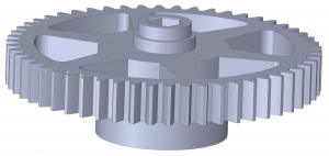
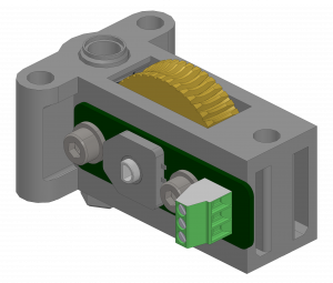
A replacement External Gear can be ordered using the Contact form.
Replace the gear as described below.
![]()
- Pull down the Drive Cover by first unscrewing three M4 bolts underneath the Drive Cover and four M4 bolts on the sides of the cover. Be careful not to drop any bolts. Tool: 2.5mm hex key (Allen wrench).
- Turn off the power to the tracker (preferably) so it doesn’t rotate when external gear/motor/sensor is not attached.
- Use a plier to cut the cable tie used for shortening the Motor’s wires.
- Unscrew the four M4 bolts attaching the Motor to the Front Plate and place the Motor on top of the Drive Cover. Tool: 3mm hex key.
- Take out the new External Gear so it is ready for use.
- Unscrew the four bolts connecting the Front Plate to the Back Plate of the external gearbox.
- Pull the Front Plate away sufficiently to remove the previous External Gear. Be careful so the plastic bushings do not fall away.
- Attach the new External Gear to the Position Sensor’s shaft first, and then attach it to the Slew Drive’s shaft.
- Reattach the four screws holding the Front Plate to the Back Plate, making sure the External Gear is correctly attached on both sides.
- Reattach the Motor with four bolts, making sure the motor shaft goes into the slot in the Back Plate.
- If the External Gear’s attachment to the Slew Drive is broken the tracker will not rotate but the Position Sensor will rotate. Therefore, if the External Gear is changed after it has been worn out the Position Sensor will then need to be recalibrated. Recalibrate the Position Sensor as described in the “Calibrating Position Sensor” section of this page.
- Reattach the Drive Cover with its seven bolts.
- Turn the power to the tracker back on.
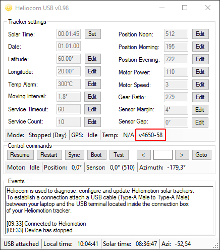
The firmware of the solar tracker can be updated using the USB connection and Heliocom. Current version of the Heliocontroller firmware is v60. The firmware version can be seen when connected to the tracker using Heliocom, ex “v4650-58” means version 58 is installed.
To update the firmware download and unzip the following software:
Heliocom: Heliocom
Bootloader: Bootloader
Heliocontroller: Heliocontroller v60
1. Run Heliocom (Heliocom v0.98.exe) and the Bootloader (HIDBootloader.exe) on a laptop. Heliocom is used to communicate with the tracker and the Bootloader is used to update the firmware.
2. Unscrew the lid to the tracker’s circuit board using the screwdriver.
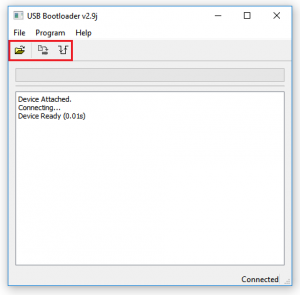
3. Connect the USB cable from the laptop to the USB port on the circuit board. Heliocom will then automatically connect to the tracker.
4. The solar tracker has four unique settings used for calibrating its Position Sensor. Please make a note of these unique values seen in Heliocom: Position Noon, Position Morning, Position Evening, and Sensor Gap. These settings will need to be manually restored after the update is complete since they will be overridden with default values.
5. In Heliocom, click the ”Boot” button and the tracker will disconnect from Heliocom and instead connect to the Bootloader application.
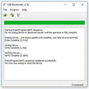
6. In the Bootloader application, click the open icon to the left of the top menu. Browse and open the latest firmware for the tracker that was downloaded earlier: “Heliocontroller-v60.hex”.
7. Click the ”Erase/Progam/Verify Device” button (second from the left) to perform the firmware update. If the update would fail for any reason restart the Bootloader and try the firmware update again.
8. When the update is complete click the ”Reset” button to the right of the menu to restart the tracker which disconnects from the bootloader and reconnect to Heliocom. Note that the version number seen in Heliocom will now have changed to read “v4650-60”.
9. In Heliocom, click 2 times consecutively on the ”Stop” button and wait a couple of seconds for the tracker to stop. The first click aborts the automatic GPS synchronization performed at startup and the second click pauses automatic tracking.
10. Change the four settings written down earlier: Position Noon, Position Morning, Position Evening, and Sensor Gap. To change a setting first click the ”Edit” button next to that setting. The field then becomes editable and the button changes name to “Set”. Type the new value into the field and click the “Set” button to submit the new setting to the tracker. Do this for all four unique parameters.
11. Click on the ”Restart” button in Heliocom to allow the tracker to resume normal operation.
12. Disconnect the USB cable and put the lid back on the box.
The motor power setting can be changed with Heliocom if more or less motor torque is needed. Default setting is “110” which translates to 20 watt (at Motor Speed: 3). Each step of “5” equates to roughly 5 watt, so setting “90” is 10 watt and “120” is 25 watt.
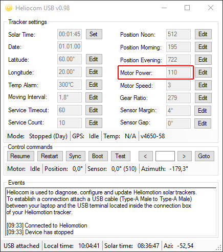
If motor power is insufficient the motor will give of a sound as it’s unable to rotate the motor shaft. If the motor power is set too high (140+) motor driver on the circuit board will not allow the motor to run until the power setting is reduced, preventing damage to the motor.
Motor strength can also be increased by raising the operation voltage of the circuit board, by turning the voltage adjustment potentiometer on the 24VDC transformer clockwise. Allowed voltage range of circuit board is 10-29 VDC. Adjusting the transformer from 24 VDC to 29 VDC will increase the motor strength linearly by 20%.
![]()
As a redundancy feature the tracker is equipped with a replaceable clock module which includes a backup battery (3V lithium cell). Should the GPS module or GPS network fail the tracker can still keep operating for many years using this clock and the stored latitude/longitude settings. Note that the tracker operates on solar time, which is different from local time. The sun always reaches its highest elevation at 12:00 solar time.
The clock module is located here on the circuit board:
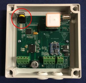
If the battery is depleted the orange LED on the circuit board blinks instead of the green LED.
The tracker will continue working even after the battery depletes. It is a redundancy in case the GPS module fails in which case the tracker will rely solely on the timekeeping of the clock module.
The clock module used is a standard “DS3231 RTC Clock Module for Raspberry PI”.
A replacement clock module can be purchased from for instance AliExpress.
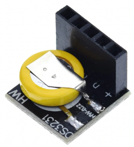
Turn off power to the tracker when replacing the RTC module. When restarted the tracker will automatically update the clock settings from GPS data and use the new module for timekeeping.
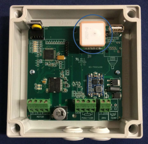
If the GPS module does not manage to synchronize to the GPS network the red LED on the circuit board is lit. The tracker can continue working for years even if the GPS module fails as it will then rely solely on the clock module for time keeping. However, the time keeping of the clock module will gradually go out of sync over the years and so a faulty GPS module should be replaced.
The GPS module is plug-and-play. Just remove the faulty module from its pins on the circuit board and plug in the new one.
A replacement GPS module can be ordered by contacting us via the Contact Form.
The tracker can be powered by any 24 VDC transformer able to provide at least 1.5A of current. The transformer supplied with the installation is the DIN-rail mounted Mean Well HDR-30-24. Make certain to turn off all AC and DC power to the distribution box before replacing the transformer.
A replacement 24VDC transformer can be purchased for instance from AliExpress.
![]()
Turn off power to the tracker before changing the circuit board. Make sure each wire is connected to the correct screw terminal as shown in the picture below before turning the power back on again.
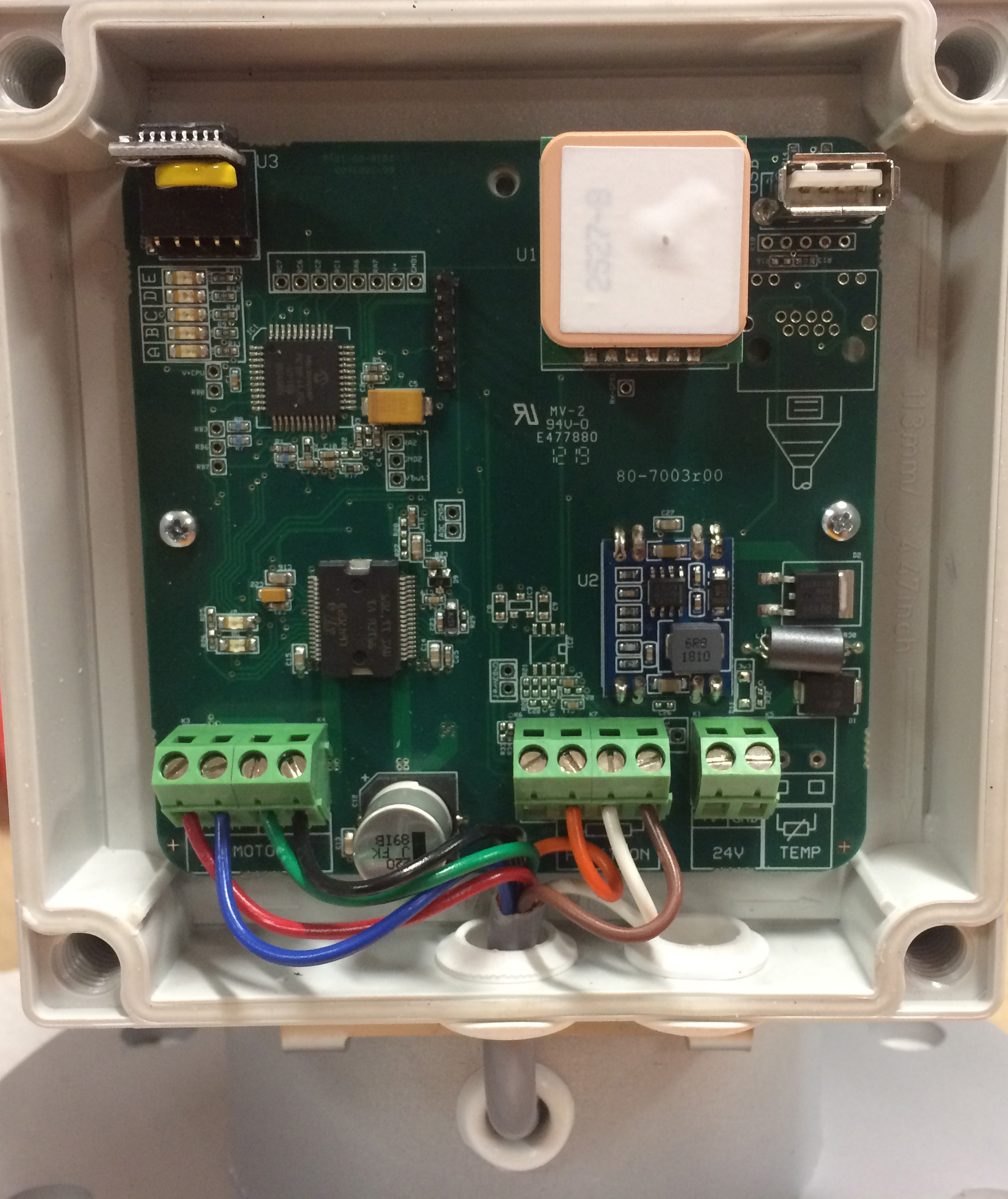
A replacement circuit board can be ordered via the Contact Form.
Specify the unique serial number of the tracker (seen on a label inside of the circuit board box, ex “Z19200”) and we will supply the circuit board with factory settings for your tracker (otherwise sensor calibration will be necessary).